So I recently came across my father’s old stash of analog SLR cameras and it occurred to me that I could probably reuse those lenses (Olympus OM 50mm f1.4 and Helios 44-2 58mm f2.0) on my NEX 5R. So after polishing up the lenses, I thought they might be useable and searched on Flickr for a similar setup. To my surprise there were quite a few sample images from the NEX 5 + OM 50mm/f1.4 and NEX 5+ Helios 44-2 combo. The Flickr samples seemed decent so I picked up a few Fotasys adapters which were really cheap (10-15) a piece and they seem to be built solidly.
Probably the only issue I have with them is that neither of the adapters really “locks” in the lens. Occasionally I can feel the OM 50mm and Helios 44-2 shift a bit at which I tighten it back on to adapter. Generally it doesn’t happen, and when the OM 50mm I didn’t have any problems with it slipping or falling off.
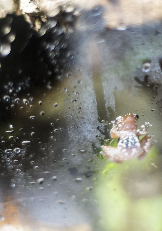
Here are a few sample images from the OM 50 f1.4.

Mount Diablo Summit Trail (OM 50mm f1.4)
OM 50mm f1.4
So as you can see the pictures are decently sharp, and the bokeh is pretty decent. These lenses retail for $50-$70 on Ebay. They aren’t expensive by any margin, but are decent fast manual prime lenses. Of course part of the beauty of these lenses is that they produce their own “style” of images and there’s something fun about using old analog SLR gear on a new digital MILC. The quirky combination works pretty well with the focus peaking on the NEX system (although not perfect).
As an Adobe Lightroom user, I’ve also been doing a lot of post processing on my images. I realized that it’s just part of photography (the digital equivalent of darkroom work) and that it’s one thing to take good images, and it’s another to enhance them to make them awesome images. Lightroom has some preset lens profiles that allow you to correct distortion, vignetting, and chromatic aberration (silhouettes and “weird” glare around objects) in Lightroom automatically. I installed the Adobe Lens Profile Downloader to see if the OM 50 f1.4 or the Helios were available, and of course they weren’t!
Adobe Lens Profile Creator
It turns out Adobe also has provided the Adobe Lens Profile Creator (ALPC) program. This program comes with calibration charts (grids) that I’ll explain in a moment, as well as some sparse documentation about how to operate the simple ALPC program. As it turns out, the program is “simple” to operate, but does not “simply” work all the time. It utilizes its own algorithms and such and there are some caveats and related trickery in getting ALPC to spit out a lens profile. In fact, ALPC confounded me for 2-3 days, before I got a working profile (calibration for one f-stop), and then an extra 2 days of experimentation to finally get everything working in one go. The rest of this blog post will delve into the details of how one creates a basic and complete lens profile for manual primes. I’ll also give some observations as to how I think ALPC is working and the most efficient way to shoot the calibration photos, and also show some workarounds I’ve tested in creating different calibration charts conveniently for proper lens calibration at a range of focal lengths. I assume these observations and work around will work equally well on zoom and wide angle lenses, because it’s all related to how I believe ALPC is programmed and what it’s trying to do mathematically at a general hand-wavy level.
So to begin I’ll describe the basic procedure summarized from the ALPC documentation. It does a decent job of describing the process, but leaves some details for you to figure out. I will try to clarify as many details as I can with some pictures, so as to hopefully help others avoid the frustration I encountered with calibrating the lenses. I mean – does anyone really enjoy generating lens calibration profiles? Probably not! But if everyone could easily (and yes, everyone can with ALPC) generate a lens profile for their lens, it would collectively save people a lot of time, and also foster further community within photography.
The basic procedure is to shoot a set of 9 images at a given setting: exposure, aperture, focus distance, and focal length. Each of the pictures should be in focus. You can import these photos and ALPC will go through each set at a particular focus distance and create a lens distortion profile based on the information. Since distortion varies based on focal length for zoom lenses, you would have to redo these sets for different focal length distances also.
ALPC Issues and possible workarounds
We’ve finally reached the portion of the blog post where I bring in the technical specifics, hackery, and process optimization together. We’ll start by looking at some of the issues and frustrations I found with ALPC.
Howto shoot proper calibration photo sets and fix chart printing errors
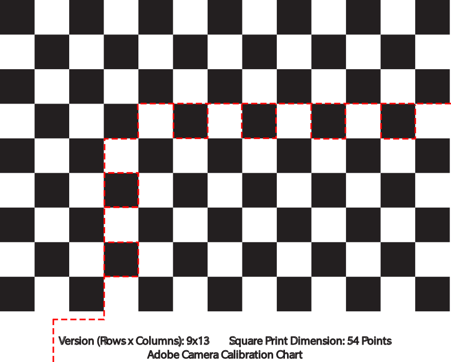
One of my initial frustrations was with the calibration charts. Initially the grids seemed a little arbitrary, but I will explain what the calibration information means. Each calibration chart label describes how many Y x X squares are on the chart. ALPC doesn’t look at the outer grid for calibrating the lens profile information. It looks at the points that are within and not on the border of the grid. This means that if there are 13 x 19 squares, that it will be looking for 11x 17 points = 187 points. Next, the label at the bottom describes how many points each square. This is related to the size of each square. A point is 1/72th of an inch. Smaller sized squares will help generate more points which will help create a more accurate lens distortion calibration profile.
Some of my frustrations were related to available calibration chart size, and also related to printing the calibration charts on 8.5×11 US letter sized paper using a laser printer. To start, if your laser printer occasionally skips over a specific line (prints it lightly) or misses a few specks here and there, ALPC will fail to find some points and mark the image as invalid. After studying which points ALPC missed (it will highlight the grid points it recognizes in yellow), I realized it was due to the missing white specks. The same occurred for a line of lightly colored printing. The solution was as simple as finding a black ball point pen and filling in the lightly-printed or white speck portions.
A separate issue is related to calibration chart size, which in turn is related to ALPC’s ability to detect geometric distortion. More on geometric distortion first, and then to calibration chart size issues which are related to different focus distances.
After correctly “fixing” my slightly mis-printed 8.5×11 calibration charts, ALPC would find all of the points. However, it would give an ambiguous error saying that there wasn’t enough variation in the images. After searching online, I couldn’t really find a good answer. As it turns out, the error is correct. In order to generate a geometric lens correction profile and proper vignetting profile, you ideally want to test the maximum distortion your lens will give you. The obvious way to do this is to compare the edges of your lens to the center, where distortion is the least. This gives you 9 obvious quadrants for imaging: the center and edges. In order to get the maximum distortion, the solution is to make sure the calibration chart (the grid portion, not including the labeling) is smaller than 1/9th of the photographic picture frame. This allows ALPC to extrapolate roughly how much distortion occurs by looking at how the grid points warp when you are not shooting the grid in the center. The documentation specifies this as a passing point, but I’d like instead to rephrase their suggestion as a necessary point. The calibration grid NEEDS to be AT LEAST 1/9th of the picture frame OR smaller. The grid doesn’t have to be EXACTLY 1/9th, as the documentation, seemed to imply. It needs to be 1/9th at the largest, but should be no bigger!
If you think about it, having a calibration grid that is smaller will still test the distortion of the lens effectively, just that there are less grid points to average the geometric and vignetting distortion parameters over, in terms of accuracy. However, you will get the same maximum distortion with the same settings whether your grid only has 5×9 points or 13×19 assuming the grid is close to the edge of the lens where distortion is obviously the greatest. The number of points just increases your accuracy, it doesn’t necessarily affect the correctness of your distortion!
To be honest, I’m can’t really think of a good reason as to why having grids that cover larger areas (over 1/9th) doesn’t work. Perhaps the algorithm implementation they are using relies on having little to no overlap. In that case, it is a weakness of the algorithm implementation rather than an issue with lens profile algorithms.
Easy quick and dirty custom-sized calibration charts
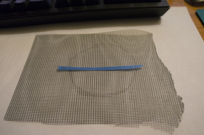
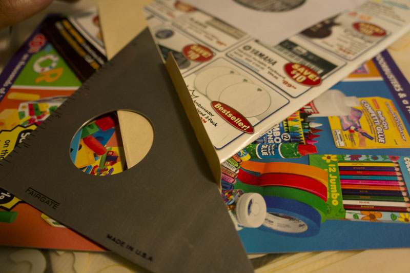
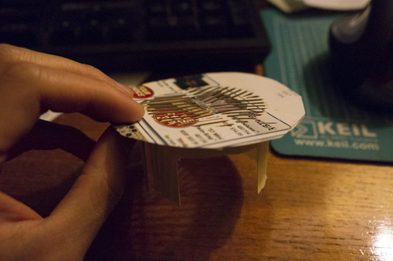
In any case, after both “fixing” calibration chart printing errors and making sure the grid is at most 1/9th the area or less allowed me to generate accurate profiles without any errors with ALPC. However, the focus distance even in the case of a 50 and 58mm prime is limited given one 13×19 54 point chart that fits on an 8.5×11 in piece of paper. Since I didn’t want to generate larger or smaller charts, I printing a second copy of the 13×19 and then set the camera up to focus on the minimal focus distance of my camera. I took a picture and then determined the dimensions of a grid that would have black squares at the corners (you’ll notice this in all the calibration charts) and would fit in 1/9th the area of the camera frame.
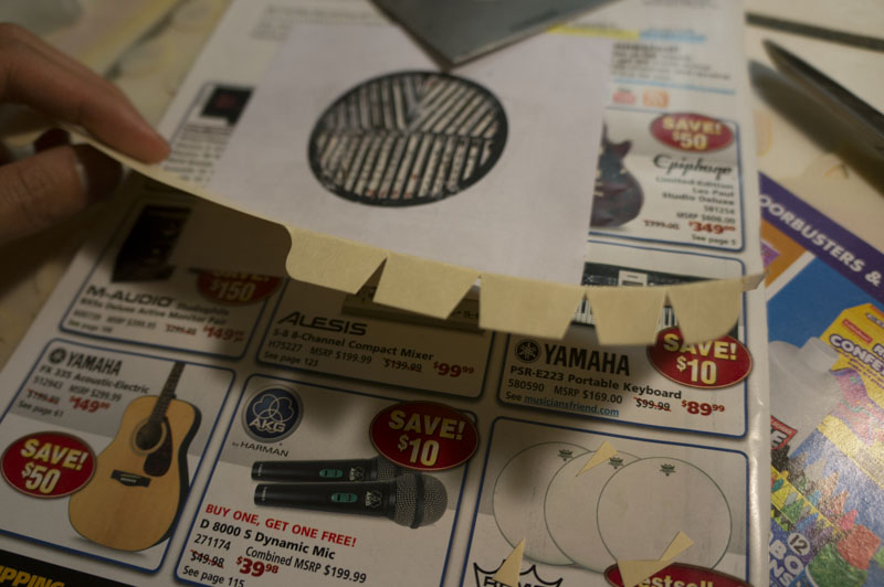
From my explanation of calibration charts before, you’ll realize that the only parameter that changes is the Y x X grid parameters. The size of the square (point (pt.) size) remains the same. After noting this, the first thing I tried was to use blue painters tape and cover up over the parts of the grid I didn’t want ALPC to recognize. I cut the grid such that painter’s tape width would easily cover up the unwanted squares. To my surprise, ALPC did not recognize any points on any of the images. My observation and reasoning behind this, is that ALPC’s algorithm to locate grids actually relies on having a white border around your grid. After locating a Y x X number of squares, it then goes in and looks for continuous black and white segments to identify grid points. This therefore explains the issues with printing errors and white specks. It confuses the algorithmic part which looks for grid points. However, the border is what determines where the grid is!
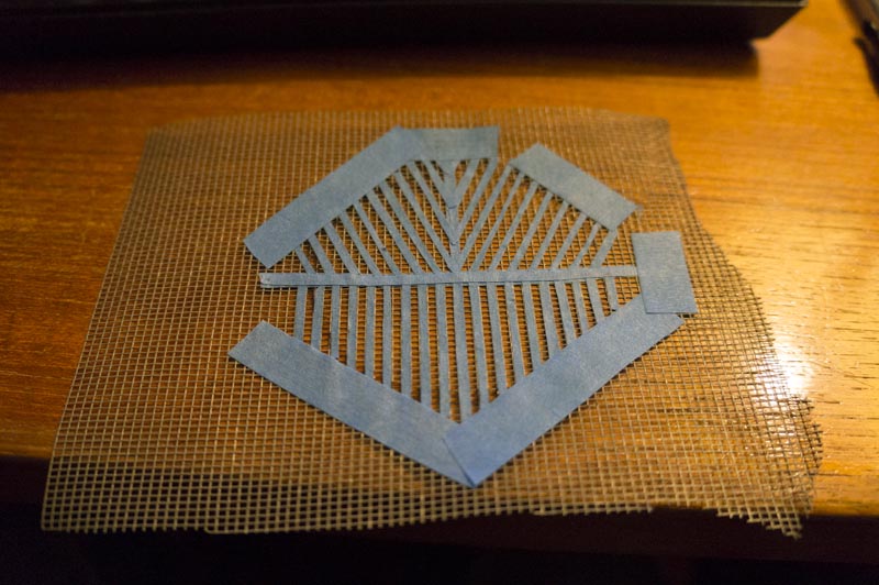
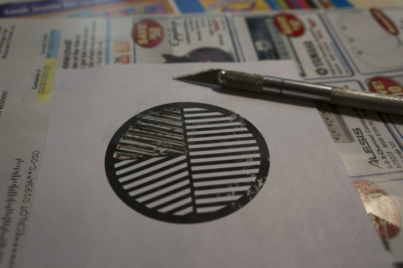
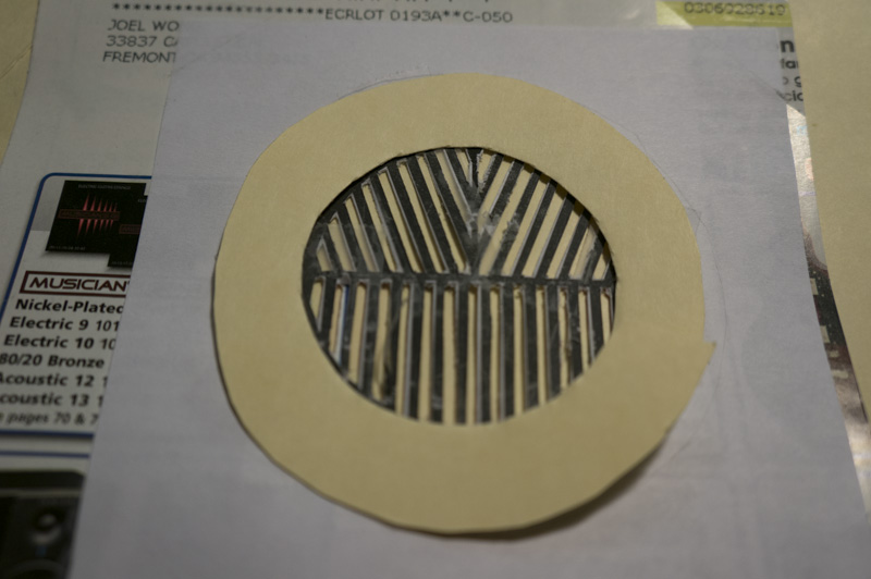
With this hypothesis, I proceeded to use a second copy of the same chart. This time I cut the grid in a specific way, so as to allow it to be taped to the wall with painters tap, without necessitating, creating custom calibration charts which you always have the option of doing. The following is a simple illustration of how one can cut a calibration chart out of a larger calibration chart and ALPC will recognize this chart properly.
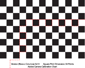
Quick ALPC custom chart hack
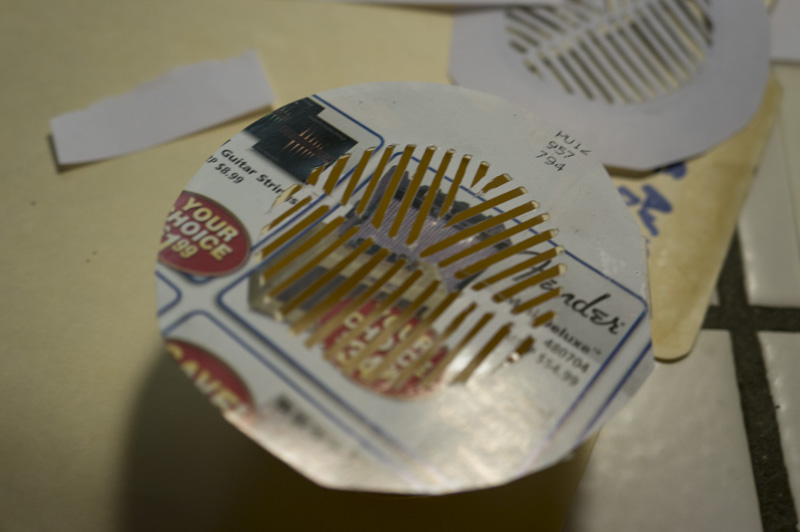
As you can see, the resulting chart is a 5 x 9 36 pt chart created from a from a 13 x 19 36 pt chart. The corners of the grid are still black squares, but ALPC is not bothered by the extra white squares attached to the grid.
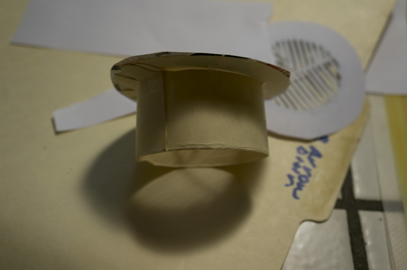
(Note: I did not test what would happen if my background isn’t white. I used a white wall for my calibration pictures, so obviously this could be a problem. The solution however is trivially simple. Just mount this grid on a 8.5×11 sized white piece of paper.)
ALPC calibration set labeling and EXIF fun
After this beautiful, elegant, and simple “hack”, ALPC was able to figure out the lens calibration parameters necessary for the images. I was able to generate lens profiles and append different focus distances to the same file.
The last issue is related to ALPC lens profile automatic naming conventions. Obvously on my fully manual legacy film primes from the late 70s, my Sony NEX 5R doesn’t know what to put for Lens Make and Model in the EXIF information. Luckily exiftool is pretty well written. I’ve created a simple python script that will add the EXIF tool to all the JPG or all the DNG files in a specific directory. Since Sony NEX5R outputs Raw (.ARW) and JPEG, I had to use Adobe DNG converter to convert all the raw files to DNG and then apply the exif tool modifications. The EXIF script I wrote allows you to simply add in the Focal Length, the focus distance (subject distance) and the aperture value along with a string the lens name. This is pretty much all the ALPC program will read from the EXIF of the pictures. Without this information, your profiles will have “undefined” for each of the focus distance groups. Importing pictures with the EXIF modified for each picture using the above script, will result in properly populated focus distance group labels. However, the Lens Make may not be properly populated.
The reason for this error, is because ALPC and Lightroom, apparently only support a limited list of Lens Makers. While the list is fairly expansive, it doesn’t cover everything. By this I mean, Russian branded Helios lenses. Olympus was supported, and so ALPC will properly populate my Olympus OM 50mm f1.4. However the Lens Make for my Helios 58mm f2 was left blank. When creating the profile of for the lens, the resulting lens profile (.lcp) file is actually an XML formatted file. Looking in the file, you will see the lens distortion parameter values and so forth. You can also view and edit the Lens Make and Creator website and so forth. What you will see, however, is that even if you modify the Lens Make later using ALPC, even before generating the lens profiles, the Lens Make will default to your Camera Make, which in my case is Sony. Now changing the XML to describe Helios didn’t show up in Lightroom, therefore, in the end I had to stick with Sony Make, and Helios as the name of the lens and the lens profile.
Here’s the link to my ALPC_modify_EXIF.py script. It is a companion script for exiftool to modify a folder of 9 images that make up a calibration set. Simply pass the folder path and filetype (.DNG or .JPG) for the corresponding filetype for your calibration set, and the script will prompt you for Focal Length, Aperture, Subject Distance (or Focus Distance) and the Lens Model Name.
Example:
python ALPC_modify_EXIF.py [calibration set location] [dng or JPG] |
Conclusion
This concludes my somewhat exhaustive study on ALPC and lens profile generation. Hopefully this has been helpful to other legacy and perhaps telescope + camera photographers. An observation I left out, is that ALPC seems to suffer from I/O bottlenecks especially when reading large number of DNG files, when performing calibration with several apertures and focus distances. Perhaps in the future, I will write a GPU/OpenCL accelerated version of geometric, vignette, and chromatic aberration lens profile. I may create a lens generator that is less picky about the size of the pictures, one that works faster, and one that is more resilient, even given a lower number of pictures. However, overall, I am satisfied with the overall lens profile correction results, and I can at least make due with ALPC as it exists. I have been happily shooting with my legacy lenses knowing that I can fix the distortion properly in Lightroom with the click of a button.